Work Hours
Monday to Friday: 7AM - 7PM
Weekend: 10AM - 5PM

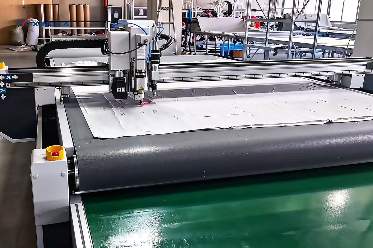
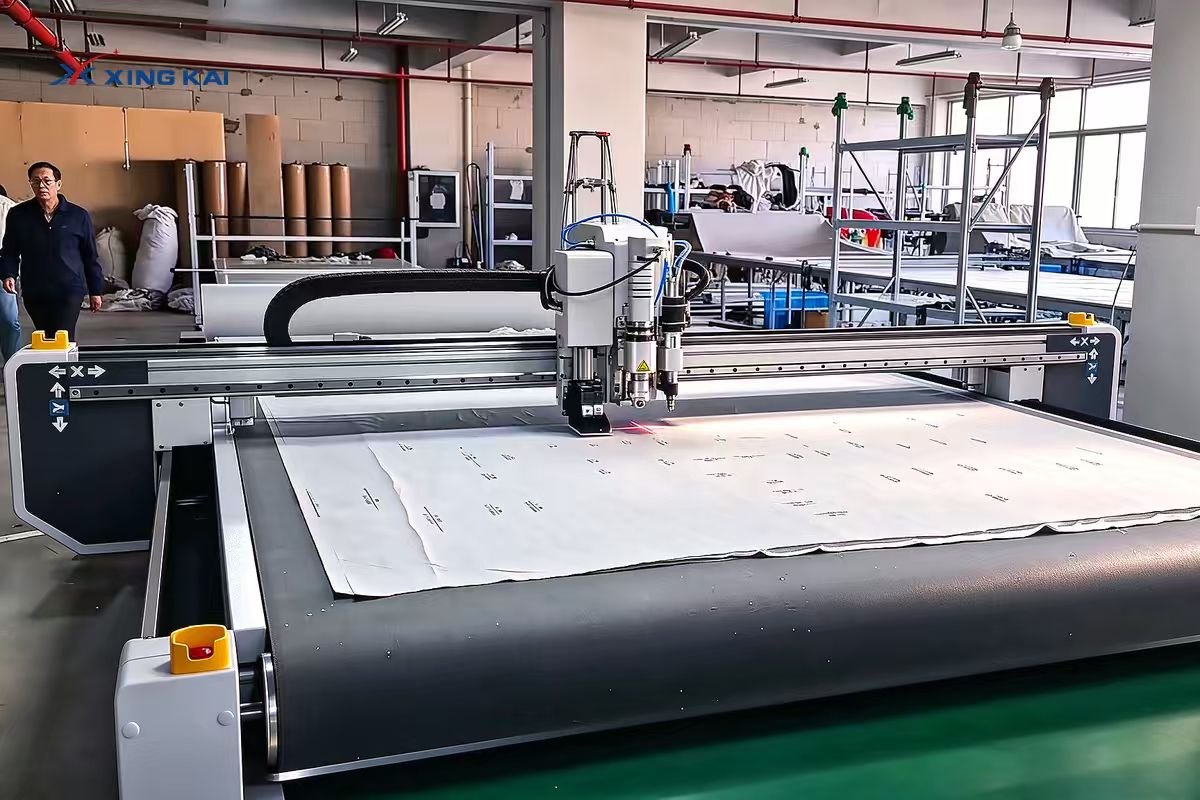
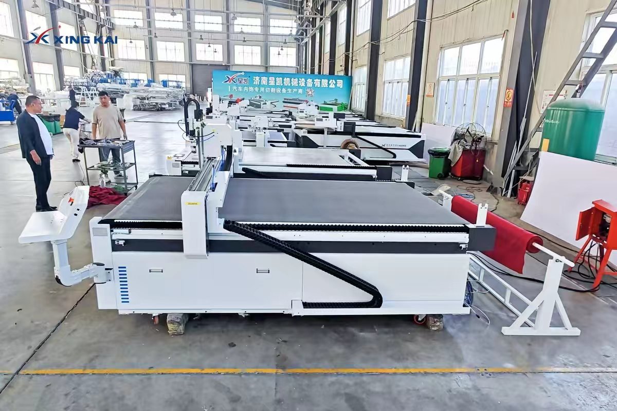
An automatic fabric cutting machine can turn a digital garment pattern into repeatable cut parts while a conveyor advances fabric through the cutting area. The Xingkai images accompanying this guide show a wide CNC knife cutter processing marked white fabric, with a moving belt and a separate collection area visible in the machine photographs. The practical question for a buyer is not simply whether the blade can follow a line. It is whether the complete process preserves grain direction, prevents fabric movement, separates parts cleanly and delivers pieces to the sewing team in the correct order.
This guide explains how to prepare a marker, choose a cutting tool, set up a roll-fed job, inspect the first pieces and estimate useful production output. It also gives a specification checklist based on Xingkai’s published XK1625 automatic-feeding textile cutter. The configuration shown in a photograph or video should always be confirmed against the quotation for the exact machine supplied.
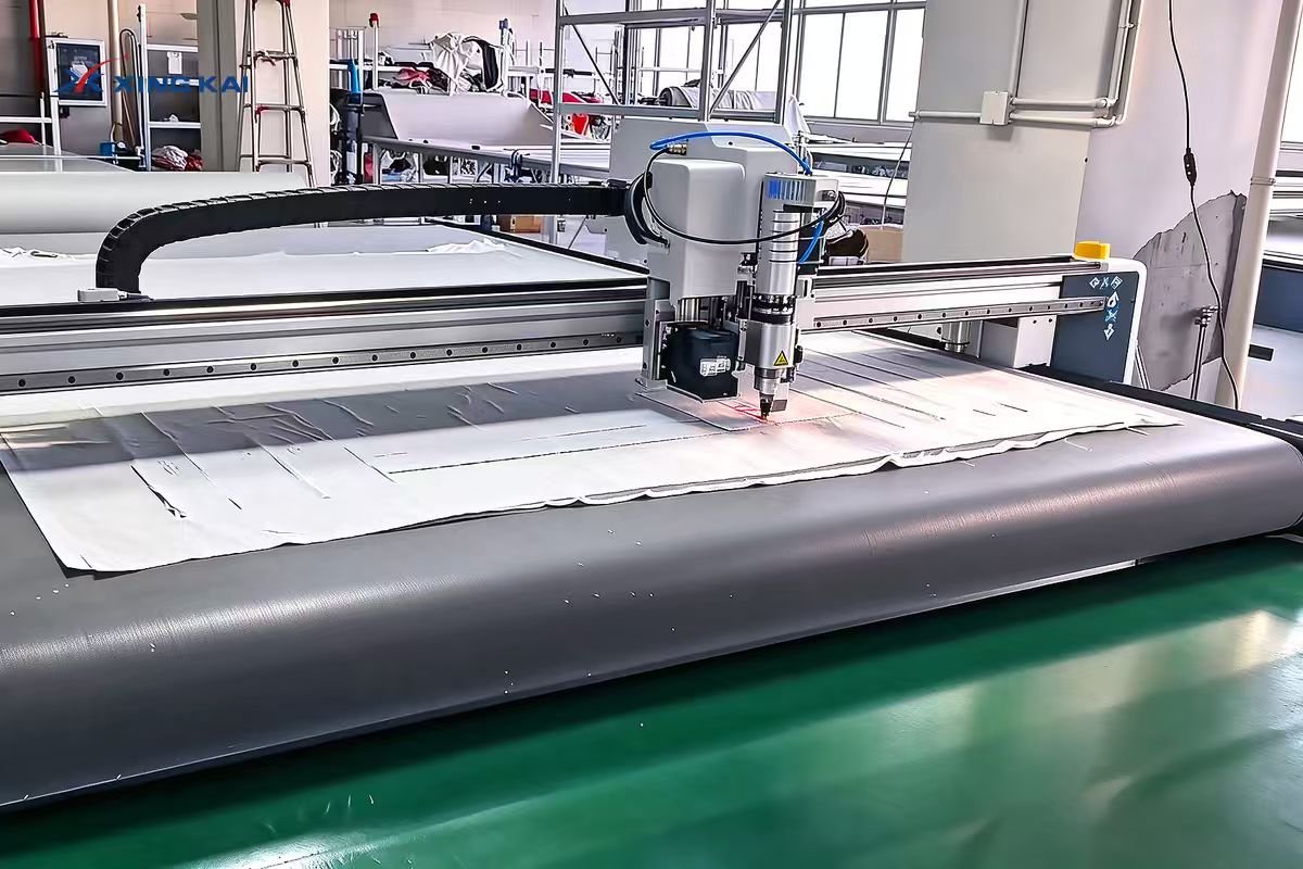
Table of Contents
- What the cutting line actually needs to accomplish
- Prepare digital patterns before nesting
- Choose the knife around the fabric
- How conveyor feeding changes the workflow
- Inspect the first article before full production
- Practical XK1625 reference specifications
- Common fabric-cutting defects and first checks
- A useful sample-cut request for a supplier
- Frequently asked questions
- Request a fabric cutting test
What the cutting line actually needs to accomplish
Cutting fabric is a sequence of controlled decisions. Before the machine starts, the production team must know the usable fabric width, grain direction, face side, stretch direction, repeat location, part quantity and seam allowance. A cutter can trace a perfect contour from an incorrect marker and still produce an unusable garment. The first production check therefore starts in the pattern file, not at the blade.
The typical roll-fed sequence is: inspect the roll; spread fabric without excessive tension; import vector patterns; nest pieces inside the usable width; assign cut and mark operations; hold the fabric on the belt; run a small test; inspect dimensions and edge quality; then continue while collecting and labeling parts. Every change of fabric construction, coating, ply count or pattern geometry deserves another test. Saved settings shorten setup, but they do not replace verification.
For a garment factory, the most valuable result is a complete, countable kit of panels. Record the number of fronts, backs, sleeves, collars or reinforcement parts required per size. If a cut part is lost at the collection end, the apparent machine speed has no value. Plan the workflow around the handoff to sewing, not only the tool path.
Start with a usable fabric specification
State the material more precisely than “polyester” or “cotton.” Two fabrics with the same fiber name can behave differently because of weave, knit structure, elastane, coating, lamination, thickness or finish. A simple test sheet should record the following:
- Construction: woven, knitted, nonwoven, coated, laminated or bonded.
- Width: nominal roll width and the narrower usable width after removing damaged or uneven edges.
- Weight and thickness: measured on the actual production lot when these affect blade choice and hold-down.
- Stretch: direction and approximate behavior under the handling tension used on the table.
- Surface: slippery, brushed, raised, adhesive, reflective, printed or delicate.
- Layer plan: one layer, a small stack, or a supported multilayer process.
- Quality limits: acceptable edge fray, notches, dimensional variation and visible marking.
Inspect at least the roll start and several positions along its length. Look for skew, bow, creases, holes, shade differences, uneven selvages and transfer print distortion. Put defects into the marker exclusions before nesting where possible. A digital cutter follows the file accurately; it cannot discover an unmarked defect by itself unless the chosen inspection or vision workflow is designed for that task.
For a stretchy knit, pay particular attention to recovery after unwinding. A piece cut while the fabric is stretched may shrink after collection. Let the test piece relax, then measure it again. For coated fabric, verify which face should contact the conveyor and whether the coating marks, drags or adheres. For a thin woven material, check whether a cut edge frays when the piece is handled by the next operator.
Prepare digital patterns before nesting
Each cut part should have one unambiguous closed contour, with separate paths for drill points, notches, internal openings or marks. Check scale, units and the latest approved pattern version before importing. Remove duplicate lines: a double path can make the tool cut the same seam twice, which wastes time and can damage a delicate edge. Check open contours, tiny segments and unintended self-intersections, especially around armholes, corners and small tabs.
Keep the sewing information with the pattern. Grain lines, part names, size labels, quantity and orientation belong in the job documentation even if they are not all cut by the knife. Differentiate cut lines from marks in the software so that a pen, punching tool or other compatible tool can perform its operation in the right order. A notching strategy must match what the sewing team expects: a small edge notch, a surface mark or a hole is not interchangeable.
For mirrored pieces, specify whether the pattern file contains both left and right pieces or whether the software is expected to mirror one. For one-way prints, nap or directional stretch, lock rotation before automatic nesting. For stripes and checks, add the required match points and reserve extra material where pattern matching is more important than maximum marker density.
Nest for good parts, not just a high percentage
Automatic nesting can reduce empty space between parts, but the highest area utilization is not always the best production result. A marker that mixes sizes without a collection plan can save fabric and create sorting errors. A tight layout may also put fragile pieces near the fabric edge or leave no room for vacuum holding. Decide which constraints are mandatory before asking software to optimize.
Use the usable width, not the printed width on the roll label. Set margins for selvages, edge curl, clamps or hold-down zones. Assign the correct quantity for every size and color. Keep grain and nap restrictions active. Where the fabric is printed, decide whether visual alignment is handled by careful placement, registration marks or an optional camera configuration. The photographs here show marked white fabric but do not establish that every machine has a camera or that the marks are registration targets.
A practical marker review asks five questions. Are all required pieces present? Are rotations permitted for this material? Are small parts still easy to identify after cutting? Can the machine hold narrow bridges or offcuts? Will the receiving operator know where one order ends and the next begins? If any answer is uncertain, adjust the marker before starting the full roll.
Choose the knife around the fabric
Xingkai’s textile product page lists several compatible tools, including an oscillating knife, rotary knife, pneumatic oscillating knife, multilayer knife, drag knife, punching tool and marking tool. Compatibility on a product page is not proof that every tool is installed on a particular machine. Select the tool combination in the purchase specification and test it on the actual material.
An oscillating knife is a useful starting point for many flexible textiles because the blade moves through the material as it follows curves and corners. A rotary knife can suit some fabrics where a rolling cut helps keep the surface stable. A drag knife may be appropriate for thin materials and simpler contours. Punching or marking is a separate decision when the pattern includes holes, reference points or assembly marks. The correct blade geometry, penetration, oscillation setting and feed speed depend on fabric construction and the required edge.
Do not choose a tool from a nominal maximum thickness alone. A compressible stack, a coated fabric and a loosely woven textile can react differently at the same measured thickness. Start with a short test containing a long straight line, an inside corner, a narrow curve, a notch and one small internal feature. Inspect the face and back of every feature. Record any fray, pull, adhesive buildup, skipped fiber or dimensional shift, then change one parameter at a time.
Hold-down is part of cut quality
Vacuum holds fabric against the conveyor surface while the head moves. It reduces movement, but it does not correct every problem in unwinding or spreading. If the roll enters with a fold, the vacuum can hold the fold in place. If the fabric is stretched during feeding, the cut part may relax afterward. If a very porous fabric leaks substantial air, the effective hold-down may need a different zone setting or a compatible overlay.
Before the first production run, check that the belt is clean, flat and free of threads or adhesive. Confirm that the active vacuum zones cover the nested area. Pull gently on an uncut corner to see whether the material creeps. Watch a short test cut at corners and around small internal pieces. If fabric lifts, do not simply increase speed or depth. Check vacuum, blade sharpness, roll tension, tool pressure and the path order.
When cutting multiple layers, verify that lower plies do not shift relative to upper plies. Measure a piece from the top and bottom of the trial stack. If dimensions or notches disagree, reduce layer count or revise the hold-down and tool setup. The published XK1625 product page lists a thickness limit, but a production-ready ply count for a particular textile must be established by sample cutting.
How conveyor feeding changes the workflow
The conveyor advances material so that the next section can be cut without manually repositioning every sheet. This is especially useful for long runs or parts longer than the active cutting window. It does not mean the machine can run without supervision. The operator still manages roll alignment, offcuts, blade condition, collection and job boundaries.
Make the feed plan explicit. Confirm the fabric enters square to the machine; set a stable unwind tension; define the usable width; choose the feed increment; and make sure the cut sequence does not release the material too early. If an outside contour is cut before internal features or marks, the separated part can move. For many jobs, internal details and marks should be completed before the final outside contour, subject to the machine software and the material test.
Long-pattern jobs require special care at the feed transition. Check that the file and software preserve registration when a part spans more than one conveyor advance. Measure across that transition, not only inside a single cutting window. Keep a sample from the beginning and the end of a run. A small feed mismatch can accumulate over many repeats even when each local cut looks clean.
The collection end matters just as much as the input end. A receiving table can keep pieces accessible and reduce crowding at the belt exit. Watch the linked demonstration below for the general fabric-cutting and collection arrangement; evaluate the exact table and handling options separately for your proposed machine.
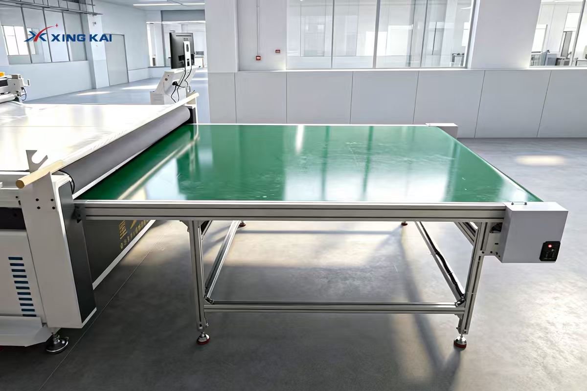
Watch the Xingkai fabric cutting and receiving-table demonstration on YouTube.
Receiving, sorting and labeling cut pieces
Set a collection rule before production. One operator may collect by garment size, another by order, and another by material color. Choose one rule and keep it visible at the machine. Label bundles with job number, pattern revision, size, color, layer count and piece count. If the factory uses barcodes or a manufacturing system, connect those identifiers to the cut job rather than relying on handwritten memory.
Keep small pieces in trays or clearly marked areas. Pieces that look alike, such as left and right facings, should not be stacked together without orientation labels. Use a first-piece reference for each size. At the end of each marker, compare actual collected quantities with the cut list. Record scrap and re-cuts immediately so the next department receives a complete kit.
Handle the freshly cut edges gently. Some fabrics fray when dragged across the receiving surface, and certain coated textiles can stick when piled while warm from the room or under pressure. The knife process itself is mechanical and does not rely on thermal cutting, but edge behavior still depends on the material. A short handoff test to sewing is the fastest way to discover whether the cut condition is truly acceptable.
Inspect the first article before full production
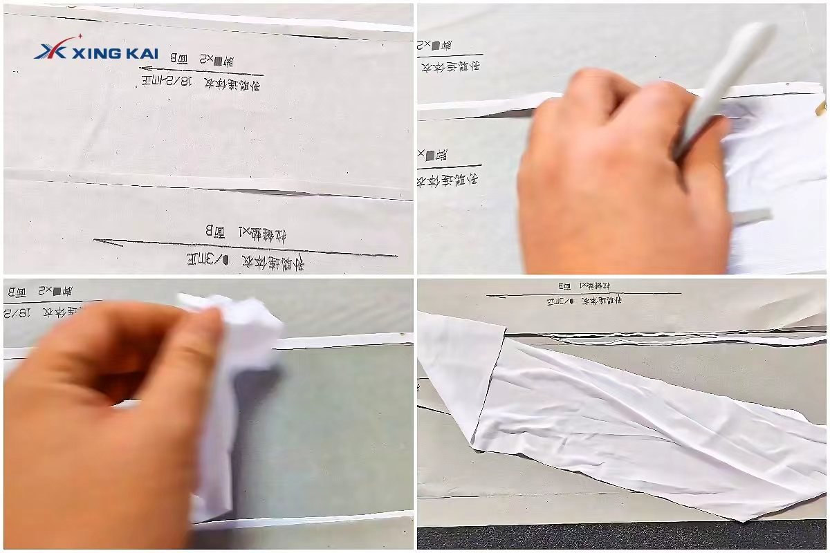
Treat the first complete marker as an approval sample. Compare the cut pieces with the approved pattern and the sewing team’s sample requirements. Measure at least one long dimension, one short dimension, an inside curve, a notch position and any mating edge. Measure a piece after it relaxes if the fabric stretches. For laminated materials, inspect the back for delamination or incomplete cutting.
Use a simple pass/fail sheet. Record job number, roll lot, file revision, operator, tool, blade condition, hold-down setting, feed setting, layer count, measured dimensions and photos of the edge. The exact tolerance should come from the product specification; do not assume a machine brochure’s positioning number is the garment’s finished-part tolerance. Fabric behavior, feed, nesting and handling all affect the measured result.
Do a sewing fit check where possible. Two panels may each measure within tolerance but fail to align because one was cut off grain or under different tension. Check the relationship between matching notches. If the sample fails, stop and identify whether the cause is pattern data, nesting orientation, fabric spread, vacuum, feed registration or blade setup. Changing the tool speed without locating the cause can conceal the real problem for a few pieces and then repeat it across the roll.
Practical XK1625 reference specifications
The Xingkai XK1625 automatic-feeding textile cutting machine is a relevant published reference for this application. Its listed working area is 1600 × 2500 mm. The page also lists vacuum adsorption with reverse air blowing, a servo and linear-guide transmission, DXF/HPGL file compatibility, and a touchscreen interface. Working sizes and tool combinations can be customized. Confirm the configuration, installed tools, actual roll width and receiving arrangement in the quotation.
| Item | Published XK1625 reference | What to verify for your job |
|---|---|---|
| Working area | 1600 × 2500 mm | Usable fabric width and longest pattern segment |
| Cutting speed | Up to 1800 mm/s, material dependent | Tested production speed on your fabric and shapes |
| Cutting thickness | Up to 30 mm, configuration dependent | Actual ply count, compression and bottom-ply quality |
| Accuracy | ±0.1 mm listed for machine | Finished-part tolerance after feeding and relaxation |
| Hold-down | Vacuum adsorption, reverse air blowing | Grip on porous or slippery fabric |
| Files | DXF, HPGL | Export from your pattern system without scale changes |
| Power | AC 220/380 V ±10%, 50 Hz | Factory supply and selected pump requirement |
| Vacuum pump | 7.5 or 9 kW listed | Final pump choice and power allocation |
| Tools | Several knife, marking and punching options | Tools included in your signed configuration |
These figures come from the product page, not a measurement of the machine in the supplied photographs. “Up to” speed and thickness are limits under suitable conditions, not a promised garment throughput. Ask for a sample-cut report on the same fabric, pattern and layer plan that your factory will use.
Estimate throughput with the complete cycle
A realistic capacity calculation includes more than head motion. Time each stage of a representative marker: roll setup, nesting confirmation, vacuum setup, cutting, feed advances, collection, inspection, labeling and any re-cuts. Divide accepted complete kits by total elapsed time. That number is more useful than quoting the maximum travel speed on a product sheet.
For example, define one production marker as a set of parts for a known quantity of garments. Run the marker three times after setup and record the elapsed time and accepted output. Note the time spent waiting for the receiving area to clear. If an operator must pause the cutter to sort pieces, a larger collection table or different bundling plan may improve output more than a faster blade setting. If the belt sits idle while the next roll is prepared, improve roll staging first.
Measure material utilization using actual consumed roll length and accepted cut pieces. Software nesting percentage does not include fabric rejected for defects, setup waste, re-cuts or trimming at the roll edge. Track these categories separately so an apparent material saving does not hide a higher rejection rate. Compare the same fabric and pattern revision when evaluating a new marker strategy.
Common fabric-cutting defects and first checks
Incomplete cut at the back of the fabric: inspect blade sharpness, tool depth, belt surface, ply count and compressed stack thickness. Do not keep increasing depth after the belt begins to show damage. Test a fresh blade and a shorter stack before revising the whole process.
Wavy or stretched panel: check unwind tension, fabric relaxation, vacuum grip and whether the marker allowed forbidden rotations. Measure after the part has rested. If the fabric is knitted or elastic, compare dimensions in both grain directions and review handling before cutting.
Frayed edge: confirm the tool type and blade condition. Reduce material movement, inspect the fabric construction and test an alternative compatible blade. Some woven edges will still require sewing or edge finishing; a cleaner cut is not the same as a permanently sealed edge.
Misplaced notches or marks: confirm the file layer assignment, scale and tool offset. Check that marking happened before the part was released. Compare notch location to a stable datum on the piece, not to a distorted offcut.
Feed-transition mismatch: check belt calibration, roll alignment and the software’s long-pattern workflow. Run a test shape across an advance line and measure it. Record the result at the start and after repeated advances to detect cumulative drift.
Parts difficult to collect: separate tiny components in the marker, use a clear receiving layout and label at the collection point. A nest that is theoretically efficient can be operationally expensive if it takes longer to sort than to cut.
A useful sample-cut request for a supplier
Send the supplier a representative material sample, not the easiest fabric in the range. Include the most demanding combination of stretch, thickness, coating or edge requirement that the machine will face. Provide a DXF or other supported vector file with a short straight segment, a tight curve, an inside corner, a notch and a typical long panel. Include the intended ply count and whether the fabric is supplied on a roll.
Ask for an unedited video of the complete sequence: loading, vacuum hold, cutting, feed advance, collection and close inspection of both faces of the finished piece. Request the measured cut parts and a note of the installed tool, blade, speed setting, feed step and test material. The sample should be evaluated against your own acceptance criteria. A short highlight clip can show the machine concept, but it cannot replace a controlled trial.
If your production includes printed motifs, stripes or checks, send the actual print. Ask how repeat alignment will be handled. A standard camera or vision option must be confirmed in the quoted machine, along with its applicable registration workflow. Do not assume that a marked fabric in a photograph proves automatic print recognition.
Decide between single-layer and multilayer cutting
Single-layer cutting simplifies visual inspection, directional placement and collection. It is often useful for samples, customized orders, printed fabric and materials that shift between plies. A compatible multilayer setup can increase output per pass, but it also raises the risk of bottom-ply deviation, incomplete cuts and difficult part separation. The right choice depends on the material and order mix rather than on a generic preference for more layers.
For a trial, prepare stacks of increasing height within the proposed machine configuration. Cut the same test pattern and measure the top, middle and bottom pieces. Inspect notches and narrow internal openings separately from the outer contour. If the lower pieces fail, find the largest stable stack that meets the product tolerance instead of using the machine’s nominal maximum cutting thickness as the production target.
Document how the stack is spread and aligned. Extra time spent building a stable stack may outweigh the cutting time saved. Also plan how cut layers will be separated and counted at the receiving table. Throughput should be based on accepted kits per hour, including spreading and collection.
Match the machine to the garment workflow
For apparel, list your largest panel, narrowest detail and most frequent fabric construction. Compare these with the working area, compatible tools and feed process. A large bed may accommodate the marker but still be inefficient if the operator cannot reach and collect parts safely. A small bed may cut the shapes but require many feed advances. The best size balances material width, part geometry and handling space.
For upholstery or automotive textile panels, long shapes and directional material can dominate the layout. Confirm how a panel longer than the active window is handled. Test a full-length part, not only a small coupon. If the factory cuts several materials on one machine, build separate settings and approval samples for each material group. Never transfer a speed or depth setting from a woven fabric to a coated composite without a trial.
Plan for routine blade changes, belt cleaning and vacuum maintenance. Keep spare blades for the materials in use and record blade life by material and job. An unexpectedly high number of re-cuts may indicate a dull blade or hold-down problem before the edge appears visibly poor. Train operators to stop when the fabric moves or the tool sound changes, rather than completing an entire marker with a known defect.
Questions to ask before ordering
- What is the usable cutting width after edge allowances on my production roll?
- Which tools are included and which are optional for my fabric, not merely compatible with the platform?
- What is the tested maximum stable ply count for my material and pattern?
- How are roll tension and feed registration controlled across long jobs?
- Is a receiving table included, and where will complete kits be counted and labeled?
- Which pattern file versions and layers can the control software import correctly?
- How are notches, reference marks and internal holes produced?
- What test results can be supplied for my target tolerance and edge requirement?
- Which vacuum pump, electrical supply and floor space are required for the final configuration?
- What training, spare blades and service instructions come with the machine?
Write the answers into the technical configuration document. A product page is a starting point, while the signed machine specification and material test define what will be delivered.
Frequently asked questions
Can a conveyor fabric cutter process fabric from a roll?
Yes, a conveyor machine configured with automatic feeding can advance suitable roll material through successive cutting areas. The roll, tension control, usable width, feed registration and receiving method must be matched to the job. A roll-fed setup still needs monitoring and a clear collection procedure.
Does an oscillating knife seal a synthetic fabric edge?
No. Mechanical knife cutting avoids the heat associated with some thermal processes, but it does not heat-seal an edge. Whether the edge frays depends on the textile construction and subsequent handling. If a sealed edge is mandatory, test a suitable finishing process separately.
What is the most useful first sample?
Use the actual production fabric and include the hardest features in one file: narrow curves, a long panel, a notch, a small opening and the intended layer count. Measure the finished parts after any normal relaxation period and inspect both sides of the cut.
Is the listed ±0.1 mm machine accuracy the tolerance of every garment panel?
No. It is a published machine specification for the referenced model. The finished fabric part is affected by material stretch, spreading, hold-down, blade setup, feed transitions and handling. Define a part tolerance in your quality plan and confirm it by sample cutting.
When should a camera be specified?
Discuss a camera or registration system when cut paths must follow printed graphics, motifs or fiducials. Confirm the compatible camera, software and print workflow in the machine quotation. Ordinary unprinted garments may not need this option.
How can a buyer compare two cutters fairly?
Supply the same material, pattern, layer count and acceptance criteria to both suppliers. Compare accepted complete kits per hour, material consumed, dimensional measurements, edge quality, collection effort and re-cut rate. Maximum travel speed by itself is not a fair comparison.
Request a Fabric Cutting Test
If you are evaluating an automatic fabric cutting machine, send your material type, usable width, maximum thickness or ply count, longest part, pattern file, daily output target and cut-edge requirements. Xingkai can use that information to recommend a working area, cutting tool, feeding method and receiving layout. Ask for a trial with the actual fabric before approving production settings.